/**/ /**/

8.30.2013

How to disassemble HP G42 or Compaq Presario CQ42 laptop

. 8.30.2013
2 comments

In the following guide I explain how to disassembly a HP G42 or Compaq Presario CQ42 laptop. Both models are very similar and all following disassembly steps should be the same or very similar for both models. In this particular case I’m taking apart a HP G42-303DX laptop. I will walk you though the following major laptop disassembly steps: 
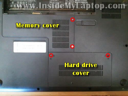
STEP 1-6: Removing laptop hard drive, DVD drive. Accessing both memory modules. STEP 7-13: Removing laptop keyboard. 
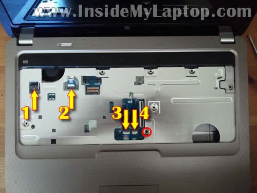
STEP 14-20: Disconnecting and removing the palmrest assembly. STEP 21-27: Removing the display assembly 
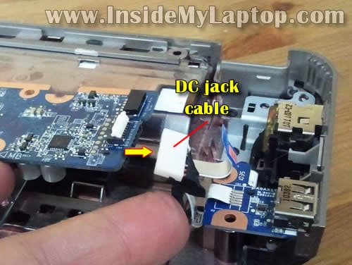
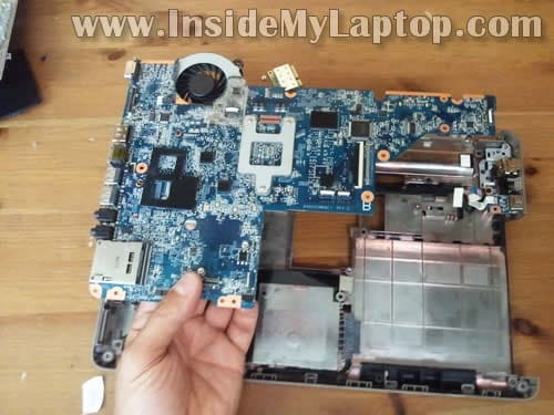
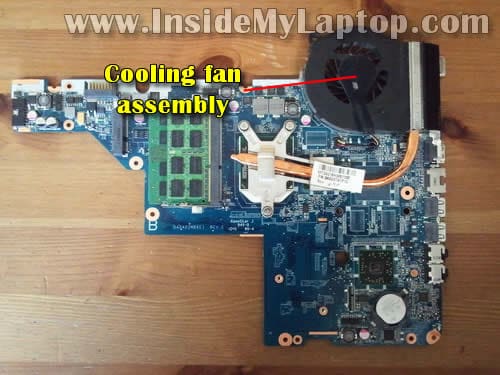
STEP 28-33: Removing laptop motherboard. Accessing the cooling module and DC power jack. Make sure the laptop is turned off before you start taking it apart. STEP 1. Unlock and remove the main battery.
STEP 2. Loosen screws securing the memory cover and hard drive cover. Lift up and remove both covers. Under those covers you can access the following laptop components: - Wireless card. - Both memory modules. - Hard drive.
STEP 3. Remove screws securing the hard drive mounting bracket to the laptop case.
STEP 4. Unplug the hard drive cable connector from the motherboard.
STEP 5. Lift up and remove the hard drive assembly.
STEP 6. Remove one screw securing the DVD drive. Push the DVD drive from the laptop with a screwdriver. Pull and remove the DVD drive.
STEP 7. Remove screws securing the keyboard on the bottom of the laptop.
STEP 8. Insert a thin and sharp object between the keyboard and laptop case and carefully lift up the keyboard.
STEP 9. Lift up the upper side of the keyboard and turn it upside down. Place the keyboard on the palmrest.
STEP 10. Now you can access the keyboard cable connector which is located underneath the keyboard. In order to remove the cable it’s necessary to unlock the connector first.
STEP 11. The keyboard cable is secured inside the connector by the retainer. Lift up the left side of the retainer with your fingernail. The retainer will open up at a 90 degree angle.
STEP 12. Now you can pull the keyboard cable from the connector.
STEP 13. Remove the keyboard.
STEP 14. Remove screws from the bottom of the laptop.
STEP 15. Remove one screw securing the palmrest assembly. Disconnect the following cables from the motherboard: 1. Speaker cable. 2. Power button board cable. 3. Touchpad cable. 4. Touchpad button board cable.
STEP 16. Disconnect the touchpad cable, touchpad button board cable and power button board cable the same way you disconnected the keyboard cable in the steps 11-12. Unlock the connector retainer.
STEP 17. Pull the cable from the connector.
STEP 18. The speaker cable has a regular male-female type connector. Unplug the male part from the female part. Do not pull by the wires. Disconnect it by the connector edges.
STEP 19. Start separating the palmrest assembly from the laptop bottom cover.
STEP 20. Remove the palmrest assembly.
On the bottom side of the palmrest assembly you can access the following laptop components: - Speaker assembly. - Power button board. - Touchpad. - Touchpad button board.
STEP 21. Start removing the display assembly with disconnecting and unrouting the wireless card antenna cables.
STEP 22. Disconnect both antenna cables from the wireless card.
STEP 23. Remove one screw securing the wireless card. Pull the wireless card from the slot. NOTE: it’s necessary to remove the wireless card in order to remove the motherboard.
STEP 24. Pull the wireless card antenna cables though the opening.
STEP 25. Disconnect the following display cables from the motherboard: 1. Video cable. 2. Microphone cable. 3. Web camera cable.
Lift up the video cable connector by the black belt and disconnect it from the motherboard.
Disconnect the microphone cable and web camera cable same way you disconnected the speaker cable in the step 18.
STEP 26. Remove four screws securing the display hinges.
STEP 27. Lift up and remove the display assembly.
STEP 28. Remove three screws securing the motherboard. Disconnect the following cables from the motherboard: 1. Optical drive (DVD drive) cable. 2. USB board cable.
STEP 29. Lift up the right side of the motherboard and disconnect the DC jack harness cable.
STEP 30. Lift up the right side of the motherboard and start removing it from the laptop bottom cover.
STEP 31. Remove the motherboard.
STEP 32. The cooling fan assembly (fan and heatsink) is mounted on the bottom side of the motherboard.
STEP 33. The DC power jack is mounted in the upper right side of the bottom cover.
Sumber Berita www.insidemylaptop.com

Read more »»
 

MY BANNER

eddie
Racun dunia is proudly powered by Blogger.com | Template by o-om.com